LM92 is digital temperature sensor manufactured by Texas Instruments. It stands out with maximum +/- 0.33° C accuracy (at 30° C) and thermostat functions with hardware output and I²C interface.
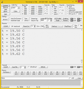
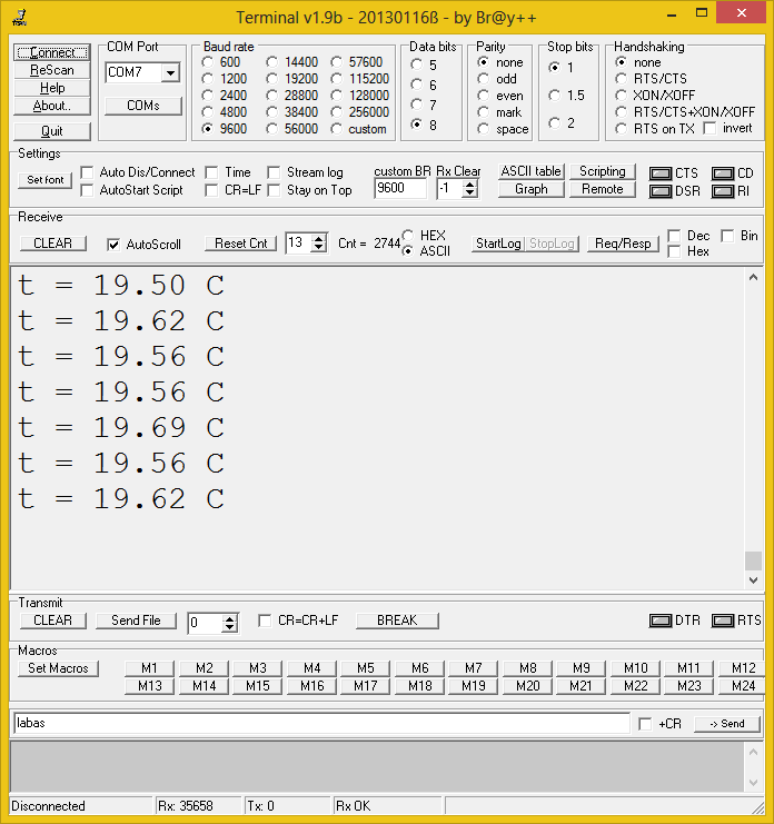
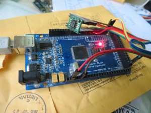
Continuous LM92 temperature reading.
I’ll show you how to just read temperature while ignoring other LM92 capabilities.
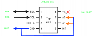
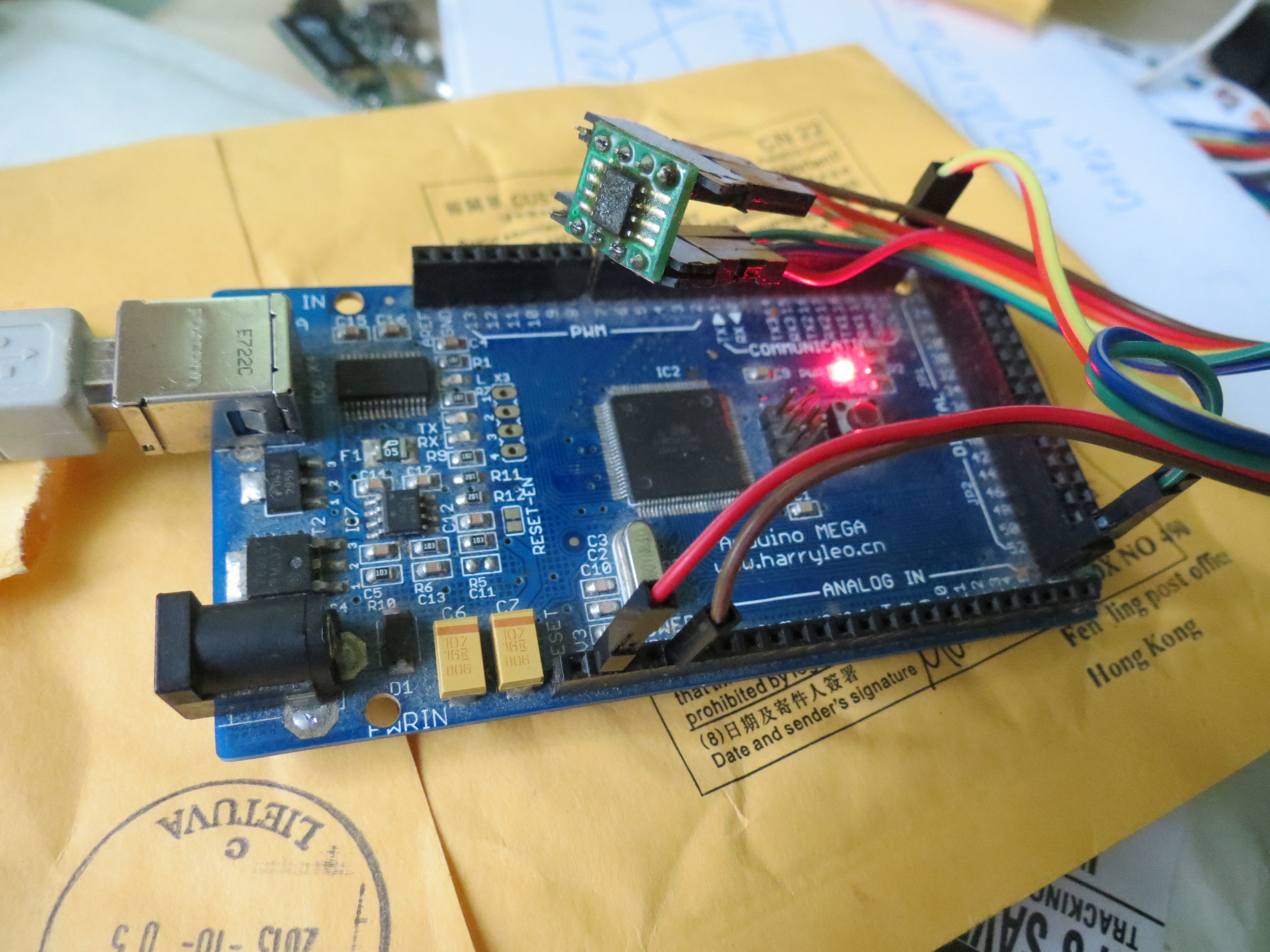
A0 and A1 pins define LM92 address for communication, by connecting pins to GND or Vss you get 4 address combinations so you can connect 4 LM92 sensors to one I²C bus. If you are planning to use only one sensor per bus just ground A0, A1 as it is shown in wiring diagram.
Other wiring is standard, although manufacture recommends 0.1 µF bypass capacitor if sensor is not near CPU.
LM92 have 7 bit slave address. Five most significant bits are “10010”. 2 least significant bits are set by A0 A1 pins. If they are connected to the ground 7 bit address is 100 1000 – 64 +8 = 72 or 0x48 (hex).
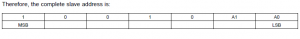
char lm92address = 0x48; //A1 A0 are grounded
I²C communication is quite simple, Arduino invoke communication by sending correct LM92 address and reading 2 bytes containing temperature data.
Wire.requestFrom(lm92address,2);

if (Wire.available())

{
for (int i=0; i<2; i++) {

buffer[i]= Wire.read();
}
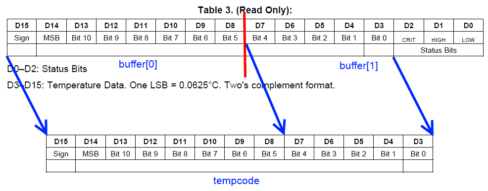
From received 16 bit temperatures register content is formated 12 bit temperature code.
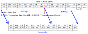
And converted to Celsius.
tempcode= ((buffer[0] << 8) + buffer[1]) >>3;
temp = tempcode * 0.0625;
Temperature from LM92 can be read at any time, but if temperature conversation is in progress reading interrupts it and it starts from beginning after reading is finished. Therefore if read request is to frequent temperature conversation never finishes. Temperature conversation time is 500 ms, so there is 500 ms delay to protect from reading to frequent.
delay(500);
Full code:
//Reading LM92. electronicsblog.net
#include <Wire.h>
#include <Serial.h>

char lm92address = 0x48; //A1 A0 are grounded
char buffer[2];
int tempcode;
float temp;

void setup() {
Wire.begin();
Serial.begin(9600);
}

void loop() {

Wire.requestFrom(lm92address,2);

if (Wire.available())

{
for (int i=0; i<2; i++) {

buffer[i]= Wire.read();
}

tempcode= ((buffer[0] << 8) + buffer[1]) >>3;
temp = tempcode * 0.0625;

Serial.print("t = ");
Serial.print(temp);
Serial.print(" C");
Serial.println();
}
delay(500);

}