Category Archives: Uncategorized

How to connect to diagnostics port of AC Stag gas controllers without special cable

Stag gas controllers have 4 pin socket for diagnostic purposes. AcGasSynchro software can be downloaded free, but you need cable/adapter to connect USB port of a computer to this special socket. If you don’t plan running automotive businesses and just curious to play with diagnostics software once or twice is not worth to buy a special cable for about 30 USD.

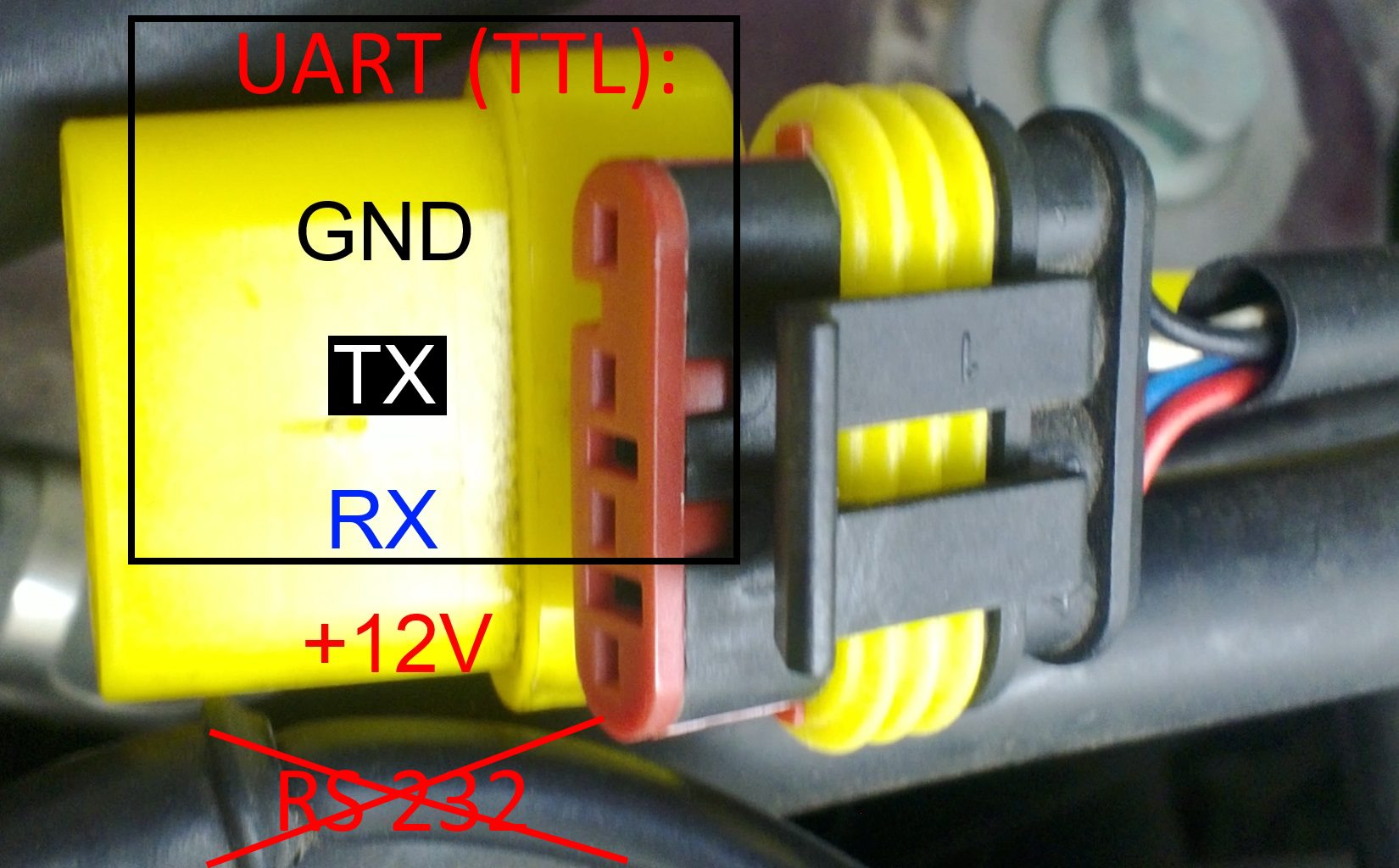
Good news that Stag gas controller use standard UART TTL level interface. So you need just easy findable USB – UART converter. Connect RX<->TX, TX<->RX, GND <-> GND, that is all.

You need a converter to UART TTL level (0/5V ), not to RS-232(-13/+13V). The RS-232 converter can permanently damage your diagnostics port and/or gas computer.

I prefer to use Arduino board because it also has integrated USB – UART converter and You don’t need to write any code, just load example “blink” project to make sure that Arduino RX, TX ports won’t interfere. You need to connect RX<->RX, TX<->TX, GND <-> GND. Don’t connect +12V wire to anything.

13090033

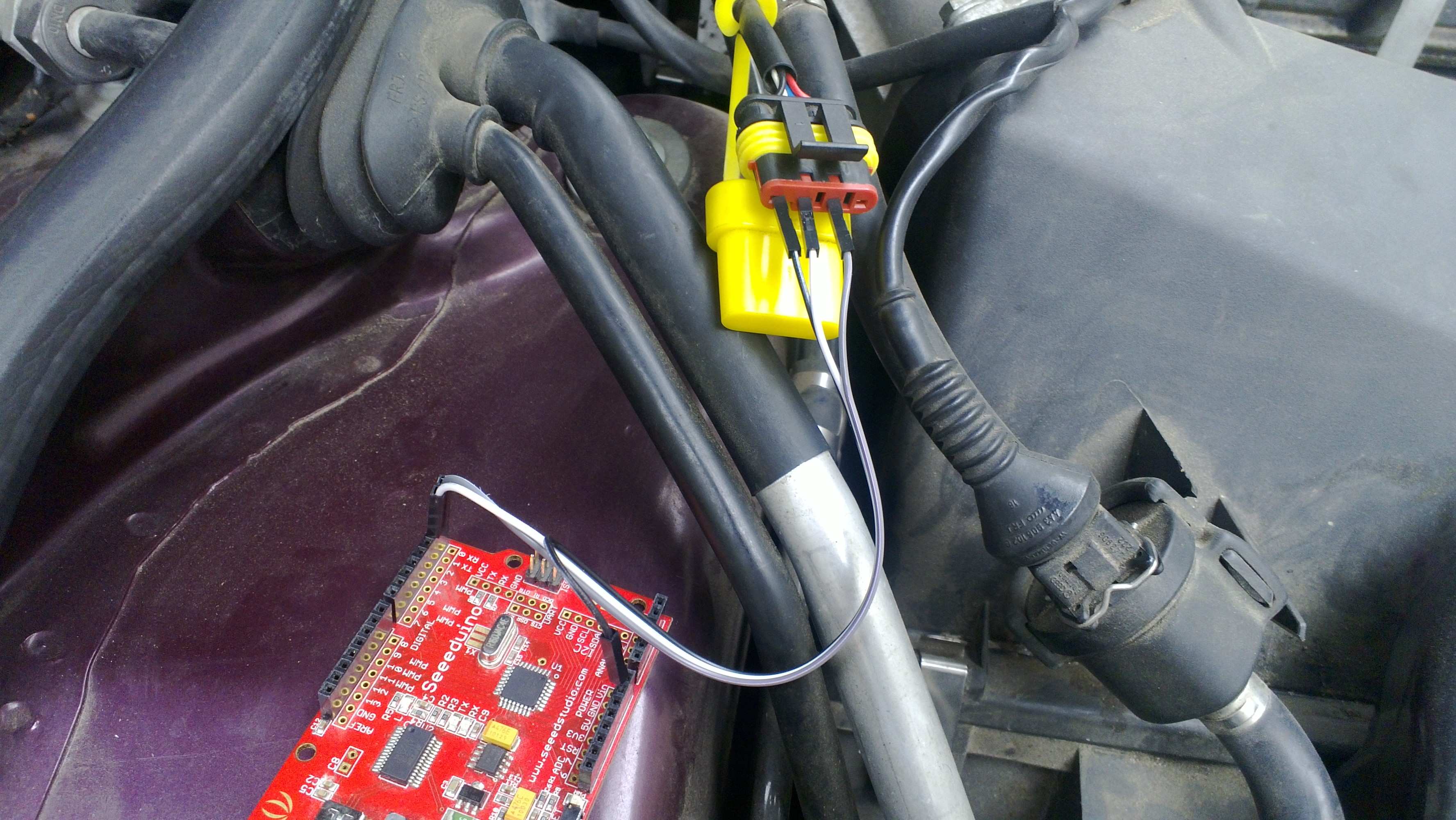
Connect Arduino board or USB -UART converter with USB cable to a computer, turn on ignition and start AcGasSynchro software.

You can turn off ignition after few second because diagnostic interface works without ignition, but goes sleep after several minutes without ignitions is turned off.
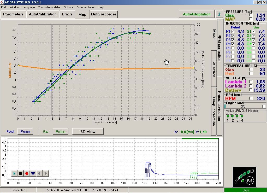
Go Port – Connect.

Software should find proper COM port what is associated with USB – UART converter and connect. If it fails to connect check if you didn’t mix up RX and TX connections, and ignition is on.

gassycnc

Now you are on your own, just remember that controller tracks logins and changes, so you can void your warranty.

You could make electric connection less messy buy using SuperSeal plug.

Cheap and used Sirf II e LP GPS Module from Ebay


I have idea to build precise clock, and GPS module is here because GPS satellites has atomic clock on board. I have chosen particularly this module, because it was the cheapest, that I could find on internet, only 15 USD with free shipping. While new GPS module costs 60 USD, thought You could find completed GPS  navigator for 70 USD.

Module has simple 5 wires connection. It’s powered from 5V, but can also work form 3.3V power supply. Data from/to device flows via well known RS-232 interface’s RX and TX data lines. Module can be directly connected to PC using RS-232 (com port), but is also needs 5V power source, USB works well. RS232 have the same data structure as UART, but voltage levels are different, so it  can’t be connected directly to microcontroller, logic level converter MAX232 must be used.

Module use standard NMEA-0183 standard interface for data transmission. One reason it’s good, because module outputs data continuously  without any request, so really it can be used only one RS232 data line.

Cold start (18 minutes until GPS fix)

To test bought GPS module I had connected it to my desktop PC RS232 port. It’s very easy to test. because seller send my with documentation and test software – GPS Diagnostics V1.05. It decrypts data in NMEA format and shows it in user friendly way.

18 minutes elapsed until I got location from module, at so called Cold start. Cold start means, that GPS module doesn’t have primary  data about time, and location, so it is impossible to calculate which of 24 satellites are in module “view”.  In this scenario module searches for signal of all 24 satellites, consequently it takes some time. Seller recommended to test device with clear view of sky, but I placed module near open window, so it is why 18 minutes 🙂

After 7 minutes I got data from 2 satellites, no location info still, but UTC date and time from satellite.

After 18 minutes location is found.

Here is module’s best result – 6 satellites, but still near open window.

Warm start (5-6 seconds)

Module saves date, time and location information in memory. Next time it is turned on it uses that information for faster GPS fix. With built in RTC (Real time clock) used time is current, not the same as was when module last time worked.

2010.10.14 update.

There is  GPS module pinout instructions from seller:

  1. Black (GND)
  2. Red (+5V)
  3. White (GPS RX Data input)
  4. Green (GPS TX Data output)
  5. Black (Shield, GND)
  6. No connect.