This short guide is about starting first project with IAR Embedded Workbench for Atmel AVR. IDE is not free, bet there is free KickStart edition with 4KB code limit.
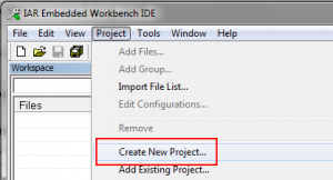
After IAR Embedded Workbench launch choose to create a new project.
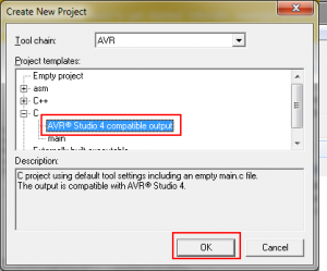
Please select “C” and AVR Studio compatible output.
Save project with desired name.
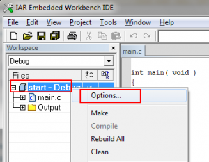
Click right mouse button on project name and select Options.
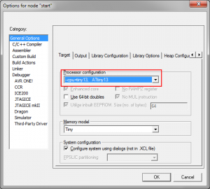
At General Options => Target select processor’s type.
At Linker ==> Output select hex format for output.
If you want to use bit definitions in code like this one:
TIMSK0 |= (1<<TOIE0);
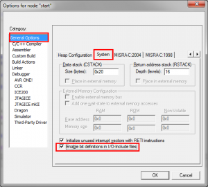
At General Options ==> System check “Enable bit definitions in I/O-include files”
That’s it for configuration. Let’s start writing code.
// Attiny13 LED blinker from https://www.electronicsblog.net/
// LED toggles every time hardware 8 bit counter overflows
//9600000/8/1024/1024 = ~1.4 Hz (overflow frequency)
// LED is connected (with resistor in series) to PB3 (pin 2)
#include <iotiny13.h>
#include <intrinsics.h>

//vector address can be found at Attiny documentation, but it must be multiplied by 2.
//http://www.atmel.com/dyn/resources/prod_documents/doc2535.pdf Page 44.
// 0x0003 TIM0_OVF Timer/Counter Overflow

#pragma vector=0x03 * 2

//timer overflow function, name doesn't matter.
__interrupt void timer_overflow(void)

{
//LED toggle
 PORTB ^= 1 << 3;

}

int main( void )
{
//global interrupts are enabled
__enable_interrupt();
//for more about timer go to http://bit.ly/atmega_timer

TIMSK0=0x02; // enabled timer overflow interrupt;
// or TIMSK0 |= (1<<TOIE0);
TCCR0A = 0x00; // normal operation (mode0);
TCNT0=0x0000; // 8it counter register
TCCR0B = 0x05; // start timer/ set clock/ prescalaer - 1024

//Attiny13 pin 2 is enabled as output

DDRB=0x08;

while (1) {

}

}
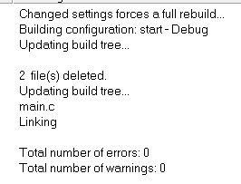
Go Project => Make or just press F7 and if everything is ok you should see something similar:
Project output file *.hex is saved in project directory you had selected at \Debug\Exe\.
Only one step left, upload program to Attiny13. I use USBasp programmer with Khazama AVR Programmer to upload program(*.hex).
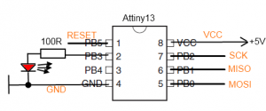
6 pins must be connected to programmer:
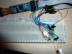
Like this 🙂
And final result:
