If You come there from internet search i assume You already know what is PWM and where it can be used, so in this post I’ll only explain how to use 8 bit timer in Atmega8 to generate PWM signal and control frequency, polarity and duty cycle.
PWM can be generated from 16-bit Timer/Counter1 or 8-bit Timer/Counter2 but this time I’ll only explain 8-bit Timer/Counter2 Fast PWM Mode.
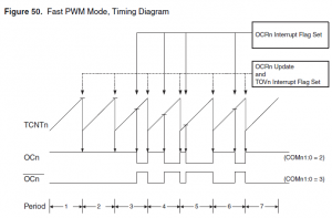
In this picture from Atmega8 documentation Fast PWM mode is explained. Counter(8bit) counts from 0x00 to 0xFF and restarts from 0x00. In not inverting mode OC2 is cleared when counter match value in OCR2 register and set at 0x00. In inverting mode OC2 is set when counter match value in OCR2 register and cleared at 0x00.
From this all turns out that PWM duty cycle depends on OCR2 register. In not inverting mode duty cycle = OCR2/256*100% and it’s 50% if OCR2 is 0x80(middle between 0x00 – 0xFF).
In every PWM period counter must count 256 steps, so frequency of signal is 256 times lower than counter clock from prescaler. PWM frequency = Atmega clock frequency/timer prescaler(1,8,32,64,128,256)/256. With 4 MHz crystal maximum(without prescaler) PWM frequency is 15 625Hz.
Register setup
For example 15 625 Hz, 50 % duty cycle, non-inverting mode PWM signal generation.
1. OCR2=0x80(128); As mentioned before duty cycle = OCR2/256*100%
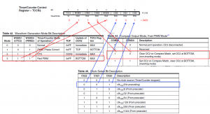
2. TCCR2=0x69;
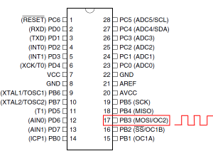
3. DDRB=0x08; PWM signal is outputted by toggling level of PORTB pin 3.
DDRB sets it as output.
All together:
#include <iom8.h>

int main( void )

{

DDRB=0x08;
OCR2=0x80;

TCCR2=0x69;

while (1) {};

}
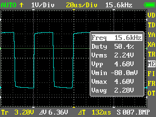
Result:
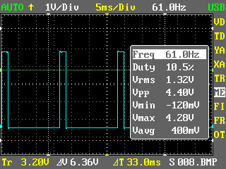
~10% duty cycle, 61 Hz.
#include <iom8.h>

int main( void )

{

DDRB=0x08;

OCR2=0x1A; // 256/10=25,6 26 in hex = 1A;

TCCR2=0x6E; // 256 prescaler
while (1) {};

}
Result:
And there is demo program and *.hex file for PWM demo seen in video.
 Atmega8 PWM demo program (1.8 KiB, 9,631 hits)
